Wednesday, 18 February 2015

Ghetto controller idea

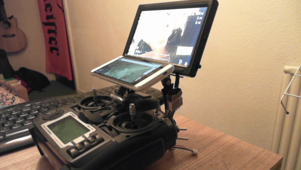
Just a short note today to show my new controller idea. It's a standard 6 channel remote but with integrated Bluetooth telemetry bridge similar to the Event38 telemetry bridge

I'm really pleased with it's simplicity and function and I've even started selling a system on ebay.co.uk

I'm also available now on LiveNinja for technical questions you have regarding Quadcopters, drones, Arduino, setup & programming and general help.

If you like it, I'm happy to make one for you and ship it. just get in touch. 

Update:
I have been using this tx for a few months now and it's great. Yesterday I opened up the transmitter and it looks interesting for programmer connections:


Perhaps it is possible to flash with custom opentx or er9x (er6x???) firmware? Or maybe using just usb cable?

I will look closer for usual VCC-GND-MOSI-MISO-SCK-RST connection points.

Then possibilities for APM Ardupilot telemetry direct from receiver like normal er9x but without frsky module costs :) :) :)


So then no need for 3dr telemetry units perhaps. Just thoughts & possibilities right now but potential super cost saving over 9x/frsky combo.

Hmmm maybe this controller has 6-pin programmer already, when using firmware usb cable? Also debug port?

Update:20 Feb 2015:
Board uses eeprom chip (for storing your programs/vehicle configurations) + 32bit ARM M0 processor @ 48mhz (Raspberrypi is also ARM 32)
Pictures:
eeprom datasheet


So er9x & open tx are currently compiled for the 9x 8-bit processor (Atmel AtMega64 8-bit MCU), so what to do?

My understandings at the moment are that the controller is connected to a PC using a USB UART/SPI/FTDI-programmer like this:
or making your own (which is what I did) like this:

then opening the firmware update file:


This connects to the remote server (there are some verisign handshaking & server commands in the code of the .exe), and replaces the existing controller firmware, so quite secure, making sure you can't easily get a copy of the firmware. Running this exe file with a network monitor program, there does not seem to be any network traffic that is specific to flysky, or at least I can't find any.

So it might seem that the exe contains the firmware.

Options are to get a copy of the firmware and then understand the type of embedded software being used and alter it, or create one from scratch by changing the bootloader, using the various embedded software available that are compatible with this arm 32-bit chip (like Eclipse IDE?? Anyone know of others?). 

The newer firmware 'v1.1 november 2014' allows ppm signal. Didn't see anything else changed. Download link here

Update:
Too difficult for me to try to decompile the firmware updater, or figure out how to flash the chip. Spent far too long thinking about it and almost fried my brain. The furthest I got was to observe the flashing process using a port monitor, and then looking at the HEX code - which makes very little sense but shows some interesting snippets:
That's as far as I am and can go, Maybe some of the guys who worked on the er9x or opentx projects can take over and do something.

Update:
Seems that the 9xrpro & Taranis all use ARM 32-bit chips so this looks good for the prospect of flashing opentx or er9x with this unit, hopefully making half the process of my goal (full telemetry data) possible. There is also a version for the very similar flysky t6 recently done, so I am excited more about this now.

I managed to hack the updater app, modify it so it looks like it a different hacker release, and also extract the firmware binary. I am able to modify text for the transmitter menus, but not to add a menu yet. 

Programmer app updated, small beginnings....

Now to modify the firmware dump I have, then replace the one in this app with my modified one (easily said, very hard to do)...Possibly this is out of my abilities, and might be better for someone who has more experience editing a firmware. 


Update:
Some people asking if possible to modify i6 with lipo/life battery. i6 Spec sheet says "Working Voltage: 1.5v x 4 AA" So this might have to be obeyed (anybody wish to test if it can take 3s lipo????? *be careful*). Safe solution to use lipo/life battery is to also use an adjustable step-down voltage regulator like this:
Then you can install any rechargeable battery you wish to. The Rhino 610mah 3s lipo seems to fit:

(You will also have to cut away the inside as it is designed to fit 4pcs AA-size batteries). Also, you will have to use 3s lipo alarm to protect your lipo from being killed.... Or just use 4x AA Nimh batteries and quit d**king about?????


Thursday, 1 January 2015

Ghetto (auto?) Retractable Landing Gear

Hello and happy New Year. Today I am going to show you how to make your own ghetto retractable landing gear for your quadcopter or multicopter.

I decided to make this article because I thought briefly about getting some retracts for my hexacopter, so I could work on coding the ardupilot to auto-retract at a set height. I am aware that the DJI S1000 does this, and that the DJI Inspire 1 has a cool retract system and well, I wanted to improve the open-source ardupilot to do the same. A stumbling block for me financially, was that a suitable retractable landing gear was going to cost me about £50/80usd. Other places are starting to release retracting landing gear such as this kickstarter project which again costs about £50/80usd if you're an early bird blah blah bah....

So how about we make our own?

We need:
2x servoless retracts bought from hobbyking for just £5 each
2x 5cm lengths of 3mm steel rod from ebay for £1
a set of m2.5 screws + bolts for mounting the servos to the copter

A couple of cm of guitar wire about 0.5mm in diameter (free thanks to the guitar shop and nail clippers hehehe)
some superglue
some hotglue from a hot glue gun
a small drill bit like this 0.6mm drill bit (£0.99 for 20 on ebay)
a drill obvs..

OK.
So, when we buy the servoless retracts from hobbyking, we see that when operated they go from zero -to- 90 degrees, in this ghetto tutorial we are going to adjust them so they are between 70-80 degrees so that they look like the expensive ones. If you are happy to have 90 degrees then you can skip this tutorial and go fly..

If you are still here, then you want to know how to adjust the angle on the retracts.

We do this by opening up the servo. We have to unscrew the top plate and unscrew the side screws, then gently as you like, open up the servo as in the bottom picture.
Inside is a long screw with a fitting in the middle and some gears on the end, we need to take that out and drill a hole in it.
This is how we drill the hole, just to show you it can be done easily. Holding the bit in some pliers will help you not make hole in your fingers.


Once we have the hole, we can take a 1cm piece of guitar wire and glue it into the hole. Leave it to set solid. like this:
This is where the magic happens. we can adjust the angle of the legs by trimming the wire to our desired needs. If you look at the servo inside, you will notice that there is a switch at either end, what the bit was doing was engaging these switches to stop the motor. By adding the pin, we can engage the switch to turn off the servo motor sooner thus reducing the angle from 90degrees, to a lesser degree. Cool huh?
Here's some filthy servo action:


So, how do we mount it to the copter? Well we bolt the servoless retract to either side of the leg mounts like this:
It's easy to connect one servo to a receiver channel right? But how do we connect two, and make them work together? You can try using a servo splitter cable if you like, but I decided to make a small PCB to link the two servos, to the receiver, and be powered by a 5v ubec. Here are some pictures:
I cut a small piece of PCB board, and used the acid etching technique to make it into a functional circuit. It's basically writing with a permanent acid resistant pen, and then dunking it into some warm etching fluid until the copper has been eaten away and leaving the penned copper lines. There's a simple tutorial here.

The legs of my copter were hot glued and the metal rod of the servos were pushed into the glue, and held until set solid. It is a good idea to rough-up the steel rod (the part that's going into the glue) so that it sticks better. You can do this by using a Dremmel tool, a saw, a bread knife, your teeth, etc etc.

And that's it really. Cost me about £12 in parts, and saved me about £38 being sent to China. I like making my own stuff, I've learned how much we just throw our money to China because we're often just too lazy to do it ourselves. Learn to make stuff and be creative, even if you mess up, or have to pay for tools, you'll learn a skill and have fun.

And here she is doing what she does best:

Update: 11/01/2015

I decided that I wanted to work on a simple auto retract system, and as I have a sonar sensor, an arduino, and a couple of servos, I put them all together and made the servo retract to 90 degrees when the sonar detects a user defined distance; in this case, under 30cm and the landing gear will lower. But you can change this value in the code.
Here's my first test:
as you can see the servo operates when the sonar detects  more/less than 30cm.

I decided to hook up two servos fixed with chopsticks as legs to show that it (kinda) works.

Here's the video:
If you want to try the code it is here.

Anyway for the life of me, I can't seem to get it to trigger the servoless retracts and i'm not sure why, or where I'm going wrong as the servoless retracts work with my 9x gear switch without a problem. Is it a pwm thing? Anyway, it works with normal servos at the moment.


update:
added fancy blinking leds to the circuit


Saturday, 13 December 2014

My Wonderbox::Idea::Code::Programming::Design::Circuit Board::Function::Prototyping


The interesting thing about making technology to your own idea is that you end up with something unique and original. For me, learning the whole process from conception & idea, design & cobbling, to actually getting a prototype made is a pretty fulfilling sensation.


I learned to code
I learned to make Circuit boards
I learned to design

And it was all put together and a neat thing was produced.

This is my wonderbox. I wanted something to measure environment variables and have various options allowing me to display data & record in various ways - micro sdcard - bluetooth - LAN - wifi - cell network -LCD display.


Some great resources out there for data collection, and for the first time we can get the hardware and it does not have to cost a fortune. Parts are recyclable for other projects, there is no waste, no throwing away. Hacking for hardware.


This is my wonderbox and it's the only one.

Thursday, 11 December 2014

Wireless data module

I made this and i'm very happy with the result. I'm looking forward to doing more with it in future DIY so watch this space.


Thursday, 4 December 2014

Blueter Voice app

Hi, here is an app I developed which allows me to control a camera shutter using an android device and a bluetooth connection. I am using a canon powershot in this instance.

I am also able to control the camera shutter using voice control. As can be seen in my video:

I hope to develop this app more in the future and I will be grateful for your thoughts and ideas. Thanks.

Wednesday, 22 October 2014

Ghetto FPV monitor (on steroids)

Hello. If you know me and my interests then you will know I like copter flying. An advancement on the standard quadcopter is to add an autopilot system, or a camera + transmitter so you can see where you fly (we call this fpv:first person view). Unfortunately, adding these components can become expensive but one thing we can do to cut the price of having such a system is to hack cheap parts and meld them into more advanced things.

Lets take the latest and greatest fpv monitor system from the beloved hobbyking website. The Quanum 7" wireless diversity monitor. It costs short of £90/$140. It consists of a basic 7" monitor, a (two of) 5.8ghz video receiver, and a battery. Can it be possible to make this ourselves and shave some bucks? Lets take a look.

We can take the classic 7" LCD car monitor screen that is doing the tried and tested rounds in FPV at the moment. - Cost = £18.73


I use one of these myself, that I bought early last year for a project. It works well for me and I'm happy with it. It comes with lots of cables and wires and you have to merge those wires with a suitable Video receiver to get a wireless video signal.

Take the classic RC305 video receiver. It costs just £12.96 now. Quite a bargain.

If we merge these two items together, we can have a wireless monitor system for just £31.69

What we need to do, is remove the circuit board from the case of the RC305 so that we can fit it neatly inside the case of the LCD monitor (It does actually fit nice & neatly).


We're going to trim and solder the 3.5mm/RCA cables so that they also join neatly inside the LCD monitor to one of it's two video inputs.

First we have to snip off the big messy wires from the back of the LCD monitor, make it nice and short and neat. Go ahead, snip off all that wire, so theres just a clean-cut nub at the back of the monitor. You will have a handful of silly waste wire in your hand.
Okay. So now we unscrew and open the back of the monitor. 2xscrews in the lower corners, 4x screws for the metal mounting plate, and 2x screws for the cable gripper.

What we have now is the insides. And what we are going to do is to merge the power wires of the monitor, with the power wires of the RC305.

We can see in my image already I haveplaced the RC305 board with a single sticky pad, connected output1 of the RC305 to video1 of the LCD monitor. The RC305 wire is Coaxial, that is, it has two wires: the outer copper shield is the ground wire, the inner core is the video feed wire.

The monitor wire is a bit different than a simple coaxial wire, but still the same principle application.
We connect the coaxial wire of the RC305 to the yellow (Video in 1), and the black (video ground). We connect the red 12v Vcc to the RC305 red power wire, and likewise, the black ground wire of the monitor to the black ground wire of the RC305. That is now done.

We now have to close up the case. To do this we have to Dremmel a few holes to accommodate the RC305 antenna & the RC305 channel select switches (top pic below). And I added a T-plug for a power connector, so I can connect it to a small 3s lipo (such as a Rhino 610mah 3s). This gives me enough power for a couple of fpv flights and isn't too heavy. You can experiment with a larger lipo if you need.
Also, I added a latching switch (bottom pic) so I can power on/off both monitor & RC305. Simple to add, just snip the red wire and add the switch between the snipped red wire. I also added a headphone jack so I could listen to the quadcopter motor sound (this lets me measure ascent/descent of the copter more accurately when out of sight). All I did for the headphone jack was to connect a female 3.5mm jack cable to the RC305 audio wire (which is the spare wire next to the video wire we cut, prepped, and connected to the monitor). 
Simples. Done! Here's the finished goods:

You can mount this to your flight transmitter how you wish (I've fashioned a holder from scrap wood previously, so no cost is required.) But in the pic below I have used a purchased mount which I like and it was only £3.11.

In total, it is less than half the price of a comparable monitor and you will have made something yourself, and learned a new crafting skill too :)

But this whole 'on steroids' thing in the title. What's that about? Well, I wanted to pimp the monitor a bit more. I added a cheap mini DVR (a measly £13.56) recorder so I could record the screen picture. It is especially good for OSD overlay recording.
Once removed from it's heavy casing, it's small and lightweight. We just connect the 3.5mm jack plugs from the RC305 to the mini DVR, and make another power link to the 3s lipo that powers the monitor.

I can't see any way that the DVR recorder will fit inside the monitor case so for now the guts and wires are a little bit visually exposed, and looks a bit messy. More a case of function over form! :)
However, I am simply going to add a made-up frame around the edge of the monitor to add depth and this should allow me to hide everything inside more neatly. So, for a DVR recording & wireless fpv monitor we have a part price of just £45.25.
From what I can gather, the cheapest dvr recording wireless monitor is the skyzone rc800 at £83.67. And we beat it with price and crafting :)

So we're pumped on steroids now perhaps?... Maybe, I have more plans.

Update: 28th October 2014
Hey, so I have thought about adding droidplanner to this setup using a touchscreen and the spare channel on the monitor; the total cost shouldn't be too great, but right now i'm not feeling like the bravado just for the sake of the bravado. Instead I have a solution that cost me zero $$$.


I decided to use a cheap phone case that I found on ebay (well.. it was my girlfriend's old one). To buy, it costs just 99p or just over a dollar.

I cut a short piece of leftover copper PCB board I had spare, and sanded it smooth so that it would fit at the correct angle for me. I drilled a hole so I could attach the piece of pcb to the neck strap hole on the 9x transmtter.


I roughed up the edge and sides of the pcb sample, and roughed up a circle in the middle of the phone holder/case as seen in the picture above. Then, I just hotglued enough glue to secure the pcb to the case and left it to set solid.


Then, it's just a 'case' (ho-ho) of attaching the holder to your neck strap mount on the transmitter. In my case I just used a motor/propeller mount holder that was close by. Above is the finished product.
It sits nicely, and is secure, and not heavy to hold. It enables me to have both fpv screen + droidplanner running at the same time. This I feel, is a lot more safe and reliable than switching the screen between the two. This way I can use the mode selection buttons to allow me to have more options in flight. So, yeah, this was a free and nice extra. Maybe I'll still do the touchscreen monitor in the future, but I figure I saved myself  from doing a $100 tutorial...For now.

Happy flying :) :) :)


Update: 14th November 2014
So I have decided that I want some fpv goggles, but I don't want to pay lots of money for a dedicated set, I just want to mash what I already have and pay just a couple of £/$. I'm ghetto, remember?

So I found this thing called a fresnel lens on ebay that cost me just £1.85 and delivered to my door in 48 hours. I figure it's what all the expensive fpv goggles use to some degree. I'm not saying this is anyway equal to those expensive goggles, but it gives a crazily immersive experience, makes the screen seem so huge that you are turning your head to glance across the image at things in view, and well, saves us about £297 of our non-existant income.
I plan on two options: the simple handheld screen enlargement mount, and head mounting google cardboard style. You can make your own. or you can buy a new, relatively cheap plastic adjustable luxury version which seems quite durable and at £15 is quite an outlay for cheap hacking.

Imagine if, at the beginning of this whole article we bought off the shelf equipment instead of mashing together? £400 vs £48.09 almost ten times cheaper, but not less than ten times the fun? I leave your thoughts up to you.


and me..
*Update: Tested fpv goggle flying with my v929 ghetto copter - it was a total vomit ride, failed to stand up on my feet, kept losing my balance, disorientation, wobbling & spinning copter, didn't have a spotter to help me, and well, now i'm having a nice cup of tea and a sit down, trying not to think about the visual experience too much *pukes*.


Next: £5/$10 Headtracking* (for PC gaming & fpv)


*when I have the parts

Update 01/02/2015
I've experimented with some DIY headtracking for games, using an mpu6050 sensor. I'm happy to say that right now, it's not ready for prime time. Workarounds don't work properly, there's no proper adjustment for exponential curves, you have to use x360ce to try to make modern games work (Crysis, Alien Isolation) and the config app crashes often. I'm not really interested in going down the rabbit hole to make this work as i'm a casual gamer these days.
As for infrared headtracking using IRleds and a webcam, i'm not at this time going down that road either.

As for using DIY headtracking to control my gimbal camera, I'm happy to suggest using the legend that is Dennis Frie's headtracker. I'm highly respecting of Dennis and his SimpleOSD work inspired me to experiment with my own OSD ideas, so I place him with legend status. 
To use the headtracker is simple, you take a nano v3.0 for just £1.99, and a GY-85 sensor for just £5.50. A total price of £7.49 for a good headtracker!!

You also need to have your Turnigy 9x flashed with er9x or opentx to allow you to plug the headtracker into the trainer port or ppm point on the 9x, but you can look up how to do that, some good guides on youtube.

Right now, i'm done with headtracking. I'm enjoying some other projects I have had ongoing which have advanced rapidly recently so i'm focussing on those and I don't really have a need for headtracking, but for discovery, further code learning and experimentation.


Wednesday, 16 July 2014

Ghetto Remote camera shutter

So, I got myself a point & shoot camera on Gumtree from an emo kid in Stockport for the princely sum of £10 (he originally wanted £15 but lost the charger by the time I arrived to collect)


Anyway, I messed about with it and it works fine even though it looks quite rough. What I was hoping to do with it in time, was to install chdk on it so that I could get more useful features out of it. I plan to strap it to my quadcopter and use it for aerial photography. Anyway, I'm digressing.

I was a bit bored last night. Think it was a full moon. And I decided to make a remote shutter for the camera so I can take photos in various scenarios that a normal point & shoot can't do. And I thought about it for a while and looked around my house for bits & bobs, and decided I could make a wireless shutter using my android phone and bluetooth to control the shutter up to a distance of 20-30 metres. Not a bad 3 hours of night time activity to expend..

Anyway, here is my result. I call it Blueter*, and the code, app and how-to is coming soon:

First video 16/07/2014


Update 03/08/2014:
Video demonstration of finished Android app. (I also have a version with voice control to upload soon but my phone is ghetto, and I need to find someone with a newer phone so I can try it.)