The interesting thing about making technology to your own idea is that you end up with something unique and original. For me, learning the whole process from conception & idea, design & cobbling, to actually getting a prototype made is a pretty fulfilling sensation.
I learned to code
I learned to make Circuit boards
I learned to design
And it was all put together and a neat thing was produced.
This is my wonderbox. I wanted something to measure environment variables and have various options allowing me to display data & record in various ways - micro sdcard - bluetooth - LAN - wifi - cell network -LCD display.
Some great resources out there for data collection, and for the first time we can get the hardware and it does not have to cost a fortune. Parts are recyclable for other projects, there is no waste, no throwing away. Hacking for hardware.
Hi, here is an app I developed which allows me to control a camera shutter using an android device and a bluetooth connection. I am using a canon powershot in this instance.
I am also able to control the camera shutter using voice control. As can be seen in my video:
I hope to develop this app more in the future and I will be grateful for your thoughts and ideas. Thanks.
Hello. If you know me and my interests then you will know I like copter flying. An advancement on the standard quadcopter is to add an autopilot system, or a camera + transmitter so you can see where you fly (we call this fpv:first person view). Unfortunately, adding these components can become expensive but one thing we can do to cut the price of having such a system is to hack cheap parts and meld them into more advanced things.
Lets take the latest and greatest fpv monitor system from the beloved hobbyking website. The Quanum 7" wireless diversity monitor. It costs short of £90/$140. It consists of a basic 7" monitor, a (two of) 5.8ghz video receiver, and a battery. Can it be possible to make this ourselves and shave some bucks? Lets take a look.
We can take the classic 7" LCD car monitor screen that is doing the tried and tested rounds in FPV at the moment. - Cost = £18.73
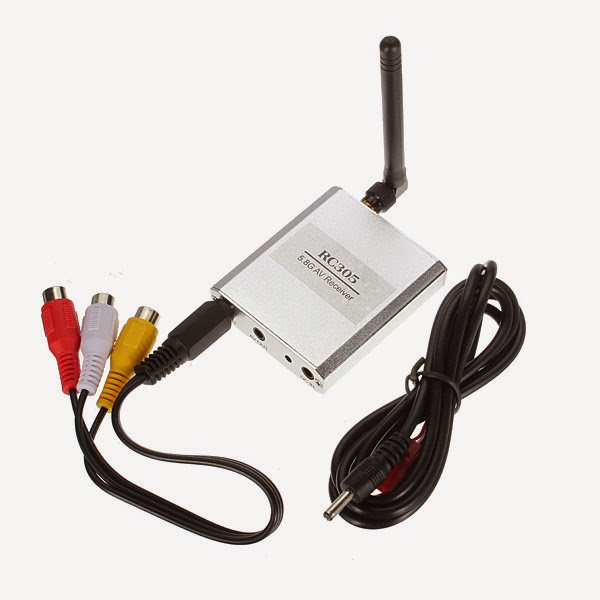
I use one of these myself, that I bought early last year for a project. It works well for me and I'm happy with it. It comes with lots of cables and wires and you have to merge those wires with a suitable Video receiver to get a wireless video signal.
If we merge these two items together, we can have a wireless monitor system for just £31.69
What we need to do, is remove the circuit board from the case of the RC305 so that we can fit it neatly inside the case of the LCD monitor (It does actually fit nice & neatly).
We're going to trim and solder the 3.5mm/RCA cables so that they also join neatly inside the LCD monitor to one of it's two video inputs.
First we have to snip off the big messy wires from the back of the LCD monitor, make it nice and short and neat. Go ahead, snip off all that wire, so theres just a clean-cut nub at the back of the monitor. You will have a handful of silly waste wire in your hand.
Okay. So now we unscrew and open the back of the monitor. 2xscrews in the lower corners, 4x screws for the metal mounting plate, and 2x screws for the cable gripper.
What we have now is the insides. And what we are going to do is to merge the power wires of the monitor, with the power wires of the RC305.
We can see in my image already I haveplaced the RC305 board with a single sticky pad, connected output1 of the RC305 to video1 of the LCD monitor. The RC305 wire is Coaxial, that is, it has two wires: the outer copper shield is the ground wire, the inner core is the video feed wire.
The monitor wire is a bit different than a simple coaxial wire, but still the same principle application.
We connect the coaxial wire of the RC305 to the yellow (Video in 1), and the black (video ground). We connect the red 12v Vcc to the RC305 red power wire, and likewise, the black ground wire of the monitor to the black ground wire of the RC305. That is now done.
We now have to close up the case. To do this we have to Dremmel a few holes to accommodate the RC305 antenna & the RC305 channel select switches (top pic below). And I added a T-plug for a power connector, so I can connect it to a small 3s lipo (such as a Rhino 610mah 3s). This gives me enough power for a couple of fpv flights and isn't too heavy. You can experiment with a larger lipo if you need.
Also, I added a latching switch (bottom pic) so I can power on/off both monitor & RC305. Simple to add, just snip the red wire and add the switch between the snipped red wire. I also added a headphone jack so I could listen to the quadcopter motor sound (this lets me measure ascent/descent of the copter more accurately when out of sight). All I did for the headphone jack was to connect a female 3.5mm jack cable to the RC305 audio wire (which is the spare wire next to the video wire we cut, prepped, and connected to the monitor).
Simples. Done! Here's the finished goods:
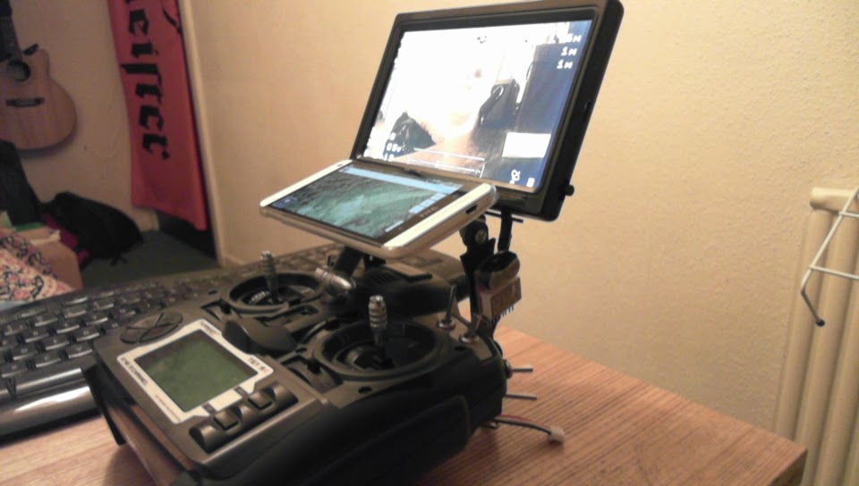
You can mount this to your flight transmitter how you wish (I've fashioned a holder from scrap wood previously, so no cost is required.) But in the pic below I have used a purchased mount which I like and it was only £3.11.
In total, it is less than half the price of a comparable monitor and you will have made something yourself, and learned a new crafting skill too :)
But this whole 'on steroids' thing in the title. What's that about? Well, I wanted to pimp the monitor a bit more. I added a cheap mini DVR (a measly £13.56) recorder so I could record the screen picture. It is especially good for OSD overlay recording.
Once removed from it's heavy casing, it's small and lightweight. We just connect the 3.5mm jack plugs from the RC305 to the mini DVR, and make another power link to the 3s lipo that powers the monitor.
I can't see any way that the DVR recorder will fit inside the monitor case so for now the guts and wires are a little bit visually exposed, and looks a bit messy. More a case of function over form! :)
However, I am simply going to add a made-up frame around the edge of the monitor to add depth and this should allow me to hide everything inside more neatly. So, for a DVR recording & wireless fpv monitor we have a part price of just £45.25.
From what I can gather, the cheapest dvr recording wireless monitor is the skyzone rc800 at £83.67. And we beat it with price and crafting :)
So we're pumped on steroids now perhaps?... Maybe, I have more plans.
Update: 28th October 2014
Hey, so I have thought about adding droidplanner to this setup using a touchscreen and the spare channel on the monitor; the total cost shouldn't be too great, but right now i'm not feeling like the bravado just for the sake of the bravado. Instead I have a solution that cost me zero $$$.
I decided to use a cheap phone case that I found on ebay (well.. it was my girlfriend's old one). To buy, it costs just 99p or just over a dollar.
I cut a short piece of leftover copper PCB board I had spare, and sanded it smooth so that it would fit at the correct angle for me. I drilled a hole so I could attach the piece of pcb to the neck strap hole on the 9x transmtter.
I roughed up the edge and sides of the pcb sample, and roughed up a circle in the middle of the phone holder/case as seen in the picture above. Then, I just hotglued enough glue to secure the pcb to the case and left it to set solid.
Then, it's just a 'case' (ho-ho) of attaching the holder to your neck strap mount on the transmitter. In my case I just used a motor/propeller mount holder that was close by. Above is the finished product.
It sits nicely, and is secure, and not heavy to hold. It enables me to have both fpv screen + droidplanner running at the same time. This I feel, is a lot more safe and reliable than switching the screen between the two. This way I can use the mode selection buttons to allow me to have more options in flight. So, yeah, this was a free and nice extra. Maybe I'll still do the touchscreen monitor in the future, but I figure I saved myself from doing a $100 tutorial...For now.
Happy flying :) :) :)
Update: 14th November 2014
So I have decided that I want some fpv goggles, but I don't want to pay lots of money for a dedicated set, I just want to mash what I already have and pay just a couple of £/$. I'm ghetto, remember?
So I found this thing called a fresnel lens on ebay that cost me just £1.85 and delivered to my door in 48 hours. I figure it's what all the expensive fpv goggles use to some degree. I'm not saying this is anyway equal to those expensive goggles, but it gives a crazily immersive experience, makes the screen seem so huge that you are turning your head to glance across the image at things in view, and well, saves us about £297 of our non-existant income.
I plan on two options: the simple handheld screen enlargement mount, and head mounting google cardboard style. You can make your own. or you can buy a new, relatively cheap plastic adjustable luxury version which seems quite durable and at £15 is quite an outlay for cheap hacking.
Imagine if, at the beginning of this whole article we bought off the shelf equipment instead of mashing together? £400 vs £48.09 almost ten times cheaper, but not less than ten times the fun? I leave your thoughts up to you.
and me..
*Update: Tested fpv goggle flying with my v929 ghetto copter - it was a total vomit ride, failed to stand up on my feet, kept losing my balance, disorientation, wobbling & spinning copter, didn't have a spotter to help me, and well, now i'm having a nice cup of tea and a sit down, trying not to think about the visual experience too much *pukes*.
Next: £5/$10 Headtracking* (for PC gaming & fpv)
*when I have the parts
Update 01/02/2015
I've experimented with some DIY headtracking for games, using an mpu6050 sensor. I'm happy to say that right now, it's not ready for prime time. Workarounds don't work properly, there's no proper adjustment for exponential curves, you have to use x360ce to try to make modern games work (Crysis, Alien Isolation) and the config app crashes often. I'm not really interested in going down the rabbit hole to make this work as i'm a casual gamer these days.
As for infrared headtracking using IRleds and a webcam, i'm not at this time going down that road either.
As for using DIY headtracking to control my gimbal camera, I'm happy to suggest using the legend that is Dennis Frie's headtracker. I'm highly respecting of Dennis and his SimpleOSD work inspired me to experiment with my own OSD ideas, so I place him with legend status.
To use the headtracker is simple, you take a nano v3.0 for just £1.99, and a GY-85 sensor for just £5.50. A total price of £7.49 for a good headtracker!!
You also need to have your Turnigy 9x flashed with er9x or opentx to allow you to plug the headtracker into the trainer port or ppm point on the 9x, but you can look up how to do that, some good guides on youtube.
Right now, i'm done with headtracking. I'm enjoying some other projects I have had ongoing which have advanced rapidly recently so i'm focussing on those and I don't really have a need for headtracking, but for discovery, further code learning and experimentation.
So, I got myself a point & shoot camera on Gumtree from an emo kid in Stockport for the princely sum of £10 (he originally wanted £15 but lost the charger by the time I arrived to collect)
Anyway, I messed about with it and it works fine even though it looks quite rough. What I was hoping to do with it in time, was to install chdk on it so that I could get more useful features out of it. I plan to strap it to my quadcopter and use it for aerial photography. Anyway, I'm digressing.
I was a bit bored last night. Think it was a full moon. And I decided to make a remote shutter for the camera so I can take photos in various scenarios that a normal point & shoot can't do. And I thought about it for a while and looked around my house for bits & bobs, and decided I could make a wireless shutter using my android phone and bluetooth to control the shutter up to a distance of 20-30 metres. Not a bad 3 hours of night time activity to expend..
Anyway, here is my result. I call it Blueter*, and the code, app and how-to is coming soon:
First video 16/07/2014
Update 03/08/2014:
Video demonstration of finished Android app. (I also have a version with voice control to upload soon but my phone is ghetto, and I need to find someone with a newer phone so I can try it.)
Call me crazy, but I just had a thought. I lost my android phone last week, but after a few days I felt like I had lost my drug addiction.
I was forced to order a new sim card & dig around my house to find an old phone to use. At first I felt crippled having to approach texting friends and inputting names & numbers. But once I had adjusted, after a few days, as it turns out, it's really quite interesting. And my Ghetto phone has a battery that lasts...I'm yet to see the battery flake out and i'm on day three. You can take your pick of these phones here.
I hated (well, disliked in general) reading on my android phone. And I mostly read using my cheap android tablet as I felt more comfortable this way on a larger 7" screen. I would mostly connect the tablet using wifi, but I would also sometimes connect using my (lost android phone's) wireless tethering ability. I hated having to update apps, allow permissions, feel frustrated with advertising, and that these apps can mostly read my text messages, emails & contact list if they wish to.
I realised how trapped and anxious (and possibly paranoid) the whole smartphone world has made me feel. Using my cheap dual-sim phone, I felt more relaxed again. Who cares if it doesn't have 4G...
Which led me to the idea.
What if I took my cheap dual-sim C1+ phone and added a small 4G router to the back, and piggy-backed my sim card?
I could take a 4G LTE dongle... Better yet. Take a 4G LTE chip like the Altair range for example, and use this in combination with a small wifi router and 1000mah lipo battery. put all this into a back sleeve for the phone and with a little bit of wonder, we have a portable 4G/LTE hotspot on your simple phone.
The dongle would operate separately from the phone, have it's own switch & usb port (for configuration), and it's own battery. If you wanted to take it off, it would be a simple snap of the phone's back cover. You could use an adapter like this one to connect the two devices & one SIM card.
"Why not get a 3G tablet?"
This would mean another sim card for me. I want to use my single sim card and use it's data allowance too. Two sim cards would mean two payments? I am aware that some phone networks are starting to issue subscribers with extra sim cards for their tablets, but it is at an extra significant (£10/$20 a month) cost. and I prefer Pay-As-You-Go, I'm not fond of monetary contracts. (Just a quick scan for UK 'phone + tablet' deals and I find that £37 per month *Measly 1GB data allowance, is the going rate. And that's a 2-YEAR CONTRACT! :(
With my PAYG provider I can choose to pay £5-£12 for varying data. £12 = Unlimited data.)
If my PAYG provider offered me two sim cards at the price I pay now, then this might be a solution. But I do quite like the idea of having a portable 4G router to use or share with my friends.
So, with a little bit of motivation....
The closest I can find to this thought at the moment is the Nokia 515. However, it doesn't support 4G or allow wireless tethering/router, only wired tethering.
*This article is of course the ramblings of a hobbyist and not to be taken as fact. You do these things at your own free will. Free will is a great thing mind you…
Something a little different. I feel I have been concentrating too much on my ghetto fpv quadcopter development, and need to do something a little bit different for a while. I have a multifuel/woodburning stove in my house and I’m very happy with it. It’s a huge Morso stove like this one:
It was bought new, and was fitted professionally, and it works flawlessly. For this privilege, it set me back several thousand pounds. I don’t need to worry if the stove is damaged, old, worn, or if the flue pipe is leaking, and various other possible scary possibilities.
Anyway, a friend of mine earlier this year, decided they too would like a wood burning stove for their house. My friend is well travelled, and has lived in some strange places, and tiny remote villages. It is fair to say that he lives a somewhat alternate lifestyle now, and believes in political conspiracy, and corporate state control. To him, everything is a lie :)
So, he decided he was going to build a woodburning stove. He bought a second-hand stove on ebay for just over £150 pounds (it’s an old 4kw stovax brunel 1a – rrp £1250). The stove looks old, worn, and needs a new baffle plate & fire bricks.
Anyway, he bought a chimney flue kit and smashed in his chimney to build his own fireplace, scaled his own roof, cleaned the chimney, and fitted the flue himself. Amazing! I thought. But mad. His stove cost him a total of about £600 to buy, fit the flue, and do the building work on the chimney. Mine cost me about £5000.
We talked about the legalities about building your own stove, and it seems, as long as you follow some general guidelines, you can indeed build your own stove without relying on a company to do it for you. No matter if a Gas company comes knocking at your door telling you otherwise (It is suggested by my friend, that it is in the interests of British Gas to try to prevent you from building a stove, and seeking out any problem they can to enable them to stop you, so you have to rely on using gas). But my friend has been out in the woods too long perhaps?
Anyway, he wasn’t completely irresponsible it seems, as he bought a couple of carbon monoxide alarms and fitted one on each floor of his house. Which led us to an idea….
We looked at these alarms, and read their instructions. It seems that what they do, is detect certain carbon monoxide levels, for certain durations. They are more of a ‘life saving’ device, than a device used for data monitoring. It seems that health & safety guidelines suggest that you should not be exposed to carbon monoxide for durations explained below:
It seems that according to the alarms he bought, the instructions suggest that the alarm will trigger if exposed to a minimum of 30ppm of Carbon Monoxide for a period of 8-hours. So, you have to wait 8-hours for the alarm to even trigger for a low level. The alarms will only trigger immediately if levels of over 4000ppm are detected.
This worried my friend and me a little bit. What we were concerned with, was low-level poisoning and it’s effects. It seems low-level poisoning can damage brain function and repair, effectively contributing to a certain level of brain damage that might be not too dissimilar to excessive alcoholism and brain damage. This is what we concluded, after several strong pints of ale and some discussion.
What we wondered was how we could read low level ppm in real-time? Like on a graph?
The alarms he bought; one has an LCD display that, when the test button is pressed, will display the ppm reading. You also get a quick short blast of the alarm too, just for good measure. It seems that pressing the button every minute to record a ppm reading (with the added alarm sound blasting your ear) is a bit impractical. What we need is a device that can record ppm and log it every few seconds.
So, me, with my electronic skills, suggested I build something that does exactly that.
It seems, that in the Arduino prototyping platform, there is a range of common gas detecting sensors available which record anything from Methane (parp) & carbon dioxide; to smoke & carbon monoxide. These sensors come under the range of MQ(X) sensors. The X being a number 1-9 to the according sensor. You can read about them here.
They are available on ebay for a couple of quid.
The MQ7 sensor that reads carbon monoxide in the range of 10-10000ppm can be connected to Arduino using only three of it’s four pins.
We can then write a program to read the sensor every, say 5 seconds and give us a ppm reading. Enough of these readings, and we can plot a graph to show how well the stove is working, if there is any damage to the stove, if there are any leaks, if someone opens a house door, if the fire is raging, or dying down. All these factors should affect low-level carbon monoxide readings in some way.
So, if we connected the MQ7 sensor to the Arduino Uno like in this diagram:
Then we upload this sketch to it >>>>> This Sketch
The sensor will print out ppm data every 5 seconds. The code works like this:The sensor it seems, needs to heat up for at least three minutes to allow it to read data properly, so the sketch begins with the following text displayed in Serial Monitor: “Sensor Heating…” for 3 minutes until the sensor is hot enough. The Arduino then makes an initial sensor reading. This initial sensor reading is made at neutral ‘carbon monoxide free’ area – i.e. outside in the open air, or similar place. The arduino then makes another reading after 5 seconds have passed, then another after a further 5 seconds, and so on.
The arduino makes a calculation: ppm reading = (5-second Sensor reading - Initial sensor reading) + 5
The ‘5’ value is used because it is assumed that a normal house will have a natural ppm reading of 2-5ppm.
It is also assumed that a house with a woodburning stove in it, will have a normal ppm reading of 7-15ppm depending on the type of stove, fuel burning used, ventilation etc.
Once we have the arduino set up and recording data, we can open the Serial Monitor and log data until we are happy:
As you can see, in my office, the readings are a normal 5ppm on average. When my wood stove is on, the readings increased to between 7-10ppm.
I decided to take the arduino round to my friends house to sample some data:
My friends stove readings were recorded over a 4-hour period. The readings went up to a high of 18ppm, and a low of 4ppm. During this period, doors were closed and opened – affecting projected room heat, and ventilation. When the door to the kitchen was opened, the reading would drop as there is a wall vent installed there.
The stove ppm would increase when the wood was burning fiercely, and the ppm reading would decrease as the fire died down to ashes -As you can see at the end of the data.
All very interesting!
In the future, I am going to repeat the sensor data recording, and use readings from the monoxide alarm that has an LCD as a comparison.
Also, in the future, I will blog a tutorial that will record the sensor data remotely over wireless Ethernet, and I will be able to view the graph in real-time using a web browser. Now this is an exciting idea.
In the mean time, feel free to have a play with the existing code, and try your own calibration experiments.
Listen to this too:
Data Logging Information:
The setup above is simple. You simply run the sketch, open Serial Monitor on your computer, collect the data, ctrl + A to select all data, ctrl + C to copy, then paste it into excel or wherever.
Saving the data to a file.
If you have a serial terminal program like CoolTerm on your computer, you can also capture to a file. To do so, open CoolTerm, and choose your serial port in the Options menu. Click the Connect icon, then from the Connection Menu, choose Capture to TextFile… and Start. Give your file a name and save.
Note: if you want the file to start from the beginning of your sketch, hold down the reset until you’ve started capture.
To stop capture, choose Connect > Capture to TextFile… > Stop. Then you can use your file in any application you want. Change the file extension to .csv and you can open it in a spreadsheet and graph as above.
Saving Data to a micro SD Card. Sometimes you want to save data when you’re not connected to a personal computer. Attaching a micro SD card to an Arduino is fairly straightforward. There are several different shields that have SD cards on board, and the Arduino Ethernet has a micro SD card on the board. The SD card library makes it simple to save files to the SD card.
Insert a freshly formatted micro sd card into your Arduino Ethernet Shield. Attach the Ethernet Shield to the Arduino Uno, connect the MQ7 sensor to the three pins (5v, GND, A0), then upload the MQ7_SDCardDataLogger sketch. This sketch reads the MQ7 sensor, and if there is an SD card present and initialized, it saves the results to a file called “DATALOG.CSV”. Transfer this file to your computer and use it as you wish. You can open it in a spreadsheet and graph it as you did above, or anything else you wish. If you just want the raw data, and no text ("ppm" "sensor heating" etc) use this file. It will take a sensor reading from the moment the logger is switched on, every 1 second, which will show how as the sensor heats up, the value quickly drops then levels out:
You can use this to make your own calibration ideas, to obtain 'true' ppm values.
Adding an LCD display & RTC Clock to this would pretty much make a complete device. Maybe I'll update this in the near future.
Saving Data online to Plotly.
If you have an Arduino ethernet shield, you can upload your data directly to Plotly in real-time. You may have heard buzzwords such as 'The Internet of Things' or 'Big Data' recently, and this is one example of this quest for finding new data about our lives. Anyway, Plotly will save your data, and allow you to make and format a graph style so that any data will be loaded into it automatically. It will even record the time that the reading was made (very handy to know without carrying a stopwatch or using a real-time-clock in your circuit). My tutorial is coming soon, but in the while we wait have a look at this tutorial so you can get to grips with using Plotly.
You can also extend the use of the Ethernet Shield with Plotly, by making it wireless. Devices like the TP-Link TL-WR702N, and this other even cheaper ebay device, can be set up as a wifi repeater, and it's Ethernet port connected directly to the Arduino. It makes this a very cheap wireless solution to send data to Plotly (considering the price of the official arduino wifi shield £80?!). You can even wirelessly tether the cheap ebay router with a mobile phone and use the 3g/4g signal, meaning you aren't even limited to house wifi connections. There are also some low-cost mini pocket routers which also connect with 3g usb dongles. There's some really neat possibilities for sensor-based data gathering. Want to collect emissions data on your local road? Or perhaps logging potential local fracking emissions? Have fun and if you think this is cool:
So, I decided to build a micro-osd for my micro fpv quadcopter. It's still in progress, but if you are interested in this project and would like to add you inputs then please visit this page: http://benbojanglesosd.blogspot.co.uk/