Thursday, 9 September 2021

Flashing a Flying X8 FY-Q7-RX receiver to a Flysky ia10 receiver


Hi, I have been given a receiver from a 'flying Fy-X8' quadcopter. The quadcopter looks like this one:

https://www.google.com/search?q=flying+fy-x8&tbm=isch&ved=2ahUKEwjansnqgePyAhUMlBoKHZogBp0Q2-cCegQIABAA

I am thinking it is similar to Flysky Ia10b receiver?
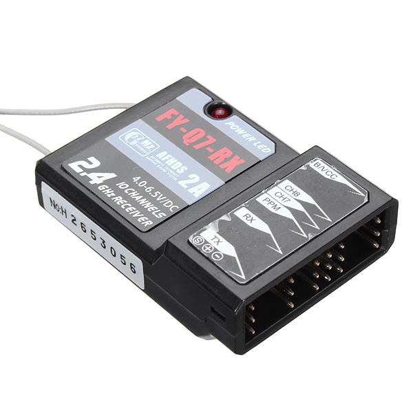
FY-X8 receiver:


  Flysky ia10b receiver:


The FY-X8 receiver has no pin connection for ibus servo/sens.
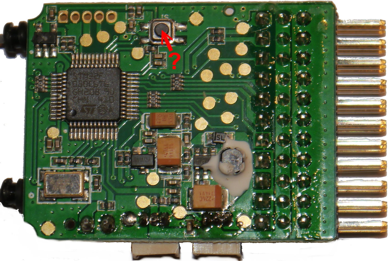
However, looking at the pcb picture there are 2 extra 3-pin pcb pads - which might suggest they are the 'missing' ibus servo/sens connections?

Do you think it is possible to flash it with ia10b firmware? I have no ia10b to compare pcb traces, just internet photos.

Both use stm32 & a7105.

I think the fy-x8 receiver is interesting because it allows ardupilot telemetry natively, so I will try to make a backup first. It just does not bind to flysky i6.

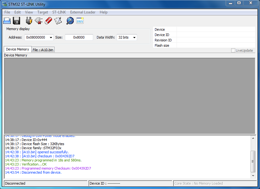
SWD pinout of FY-Q7-RX receiver:

Connection to ST Link V2 Programmer guide here:
http://www.multirotorguide.com/guide/flysky-receivers-rssi-mod-alternative-firmware/

oh cool were in. I had to change to software system reset from hardware system reset in ST Link settings.


here's the original firmware:

do you thik it can be changed to pair with the flysky i6 somehow? I probably shouldn't try flashing with ia10b firmware until the original bin file has been looked at.
 
I think it only binds to the flying fy x8 transmitter, it looks like a flysky i6
 
Flying X8 Transmitter:
Flying X8 it has telemetry, the receiver directly connects to tx and rx on an APM board. There seems to be two versions of FY-Q7-RX receiver, one with six signal pins:


and one that I have with more pins similar to the ia10b:
interestingly, my receiver with more pins, it has a sticker over the old sticker like this:


The Flying X8 transmitter displays APM telemetry on screen:

I think qba667 made MavlinkToibus to allow APM telemetry through an ia6b receiver using an arduino pro micro between ia6b and APM:
https://www.rcgroups.com/forums/showthread.php?3020949-FlyPlus-firmware-for-FlySky-I6X
https://github.com/qba667/MAVLinkToIbus

Somebody here attempted to flash the transmitter with 10ch mod firmware and succeeded, but I am unsure if they backed up the original TX firmware firstly:
https://translate.google.com/translate?hl=en&sl=auto&tl=en&u=https%3A%2F%2Fladecadence.net%2Fblog%2Fflasheando-una-flying3d-fy-q7%2F

Somebody on rcgroups seems to think the receiver is also similar to fs-ia10b:
 

Also seems accroding to rcgroups comment that binding plug of receiver goes not to pin B/Vcc like normal receivers, but to port marked Tx:


So I shall try this also.

edit: tried binding plug via Tx but no fast led flashing on the rx, so false alarm on my version of rx. bind plug on B/Vcc as normal makes fast led flashing happen/bind mode.
Holding down button on rx before powering makes led flash three times repeatedly, so perhaps this is update mode. Same on ia10b perhaps.

Later in the Day...

more internet searches and it seems there are also 2 versions of flysky ia10 receiver, 1)ia10 and 2)ia10b:

FS-ia10 receiver:


ia10b receiver:

Seems the FY-Q7-RX is more similar to ia10 receiver, the ia10 even has the two side inputs same as FY-Q7-RX:

 I have not seen ia10 before, and have not found any images of the internal pcb yet.

Later in the day....

I managed to find photos of fs-ia10 receiver pcb:


 FY-Q7-RX and Flysky ia10 receiver have identical pcb:


Later in the Day.....

If anybody has ia10 receiver and can make fimware copy?
Or knows if ia10b firmware working with ia10?

interested to see what differences are between ia10 firmware and FY-Q7-RX

Later....

Nevermind I think I found the ia10.bin file on the internet:
https://www.dropbox.com/s/fyohbyzr3rievf5/iA10.bin?dl=0

I will try to flash it to my funky receiver soon.

update: So actually if ia10.bin will flash to FY-Q7-RX, and original FY_Q7_RX_Original_Firmware.bin will flash to ia10 receiver
There is then no reason why the flysky transmitter cannot be flashed with flying X8 tx firmware
Then all we have to do is connect Ardupilot APM board rx/tx to receiver and we get APM telemetry on Transmitter...See.

 Neat. So I can flash original ia10.bin firmware to FY-Q7-RX receiver:


 Solid LED after binding to Flysky i6 transmitter:

PPM 8 channels on receiver pin 1 working.

I guess it is now a Flysky FS-ia10 for no money.

I will test ibus also but I have to solder dupont connector to the pcb pads first.

Also, after I have done this I will try and flash FY-Q7-RX_original_Firmware.bin back to see if works.

I would like to somehow find a Flying X8 FY-Q7 transmitter firmware and flash that to the Flysky i6 Transmitter, then connect to my pixhawk and see what telemetry comes to the transmitter screen.

I will check if ia10.bin includes rssi and post again.

Edit: It does RSSI. Here is the firmware

Edit2: 14ch iBus working, pinout:

Update3: Mod_ia10 receiver goes into rebind mode if both tx & Rx are switched off. Automatically goes into fast flashing led bind mode, but that's not so bad, just hold bind button on Flysky i6 when switching on and it binds.

Update4: Intv (Receiver voltage) on Flysky i6 displays just 10% of connected battery, in my instance I powered with 1s 18650 @ 3.8v, but the flysky i6 Transmitter shows as 0.38v. Wonder what is happening there. No biggie, if I do voltage mod on the receiver perhaps it will show real voltage? 

FY-Q7 flashed with ia10 firmware. Notice Intv as 0.38v but the 18650 is actually 3.8v. I wonder if there is a PCB resistor difference somewhere I did not see, or is it just software voltage calculation difference?

To be continued..... 

Update:
I am starting to examine the binary file of the FY-Q7.bin firmware. I notice that although the .bin file is 32kb there are lots of FFFFFFFF compared to ia10.bin which is also 32kb. There are of course differences to the two .bin files. I would like to figure out how to bind with Flysky i6 transmitter so I can see if it has ibus function removed or other features, perhaps it is only PPM + PWM + Serial Telemetry? This would match the APM protocol from back in the day, ibus on Ardupilot was only implemented at V4.00 of Arducopter I believe, so it was not needed. The PWM channels would be to control the Gimbal I guess.

After looking at the binary file I noticed a difference in the FY-Q7 firmware at offset 0x204 that ia10.bin or ia6b.bin (or any other flysky firmware I seen) does not have. ia10 and ia6b are 03000100 but FY-Q7 is 02000100
By changing FY-Q7 firmware offset 0x204 to 03000100 i thought this might be the difference between binding and not binding but not successful.
Any thoughts?

I am able to flash to and from ia10.bin & FY-Q7.bin without problems.

 To be continued...

Saturday, 24 April 2021

Some ghetto musings on a budget antenna

 Sometimes, creating a product is the easy part. Completing the distribution, packaging, sales or returns can be the bit that causes you the most difficulty. I'm lucky enough to have time in lockdown to think up mad inventions and ideas. Mostly they are done, and put on a shelf to collect dust for a while, looked at and thought about, considered and sometimes forgotten about. That's life. Product innovation, hobby Diy, we make things, we break things, we succeed and we defer success. I was fortunate enough last month to complete a design for a Meteor-M2 antenna I had been thinking about for a while using a combination of junk parts, precision calculations, cad design, 3d printing, and some thought. I wanted to make an antenna which would receive the Meteor-M2 weather satellite but improve on previous ideas, have excellent signal strength, and a few other things in my tick box such as making it lightweight, foldable, compact, and cheap to reproduce. For me, making it have good signal strength was the easy part. The Meteor satellite has a super powerful transmitter and all I really had to do was match the Frequency & polarisation.

Making it foldable and compact, I thought long about different ideas, cost effectiveness, financial risk, and simplicity. I considered using an array of folding, telescopic radio antennas but even those, when factoring in 8 of them for the final design would bump the cost up-past where I was prepared to expend, afterall it might not even work at all. But after a while of thought I found a novel solution in using metal roller DIY tape measures as the antenna elements. This would allow me to have them fold into the main body of the antenna and be more compact, not sticking out permanently like a 1.2m clothes washing horse most likely laying in the shed and obstructing everything. It is also dirt dirt cheap to use metal tape measure sections as antenna elements; pennies. So with a little bit of computer design, 3d printing, diy & plumbing store purchases I set about making this Meteor-M2 antenna.

It worked really well, it was lightweight, cheap, self made, there is really nothing I can complain about. it must cost just £1 in materials to make a single antenna. Yipee.

Anyway, I thought about my antenna for a while, and thought about where I wanted to go with it, what comes next, and I realised that I wanted to have some HAM radio components for a long time now, but have never considered buying them, they always just seem to be just out of reach enough for me not to be able to spend that amount of money on them - i'm talking about Airspys, SDRplays, LimeSDR minis, HackRFs, LNAs, Nooelecs, XRIT Decombobulators so on and so on. Those things were a dream to me and as they cost more than double or triple the price of say a Raspberry Pi or a Jetson Nano, I thought what use would they be to me long term like these wonderful little linux devices are. So I put them off, forgot about them, and quashed desire. 

But then, after making this antenna, and showing it to the Amateur radio community on a Facebook group, I felt kinda disheartened. Lots and lots of nice comments from some really cool radio amateurs. But also here and there were the begging messages "STL????" "Can U Please Post Design Files Plzz..Thnk U Friend." I looked at these Facebook profiles of the begging messengers and quickly saw that these guys are not poor! They have all the gadgets, all the houses, all the jobs. They are just riding a wave of 'give me more of your stuff!'. I wonder sometimes that these people are going to sail through life of a free meal ticket and do it so cleverley that they are gone before anyone even realised. True geniuses are the Men who sell the Eiffel Tower Twice

So I thought screw that.

I decided that I would make a few of my super advanced junk antennas, churn them out, and sell them on the old efrikkinbay. I chose a pricing to support my efforts, the time it takes to 3D Print the parts, My material costs such as tape measure, pipes, coax cable & connectors. Also I factored in enough to cover postage fees, ebay fees, paypal fees; which take as much as 25% or more of the sale value. My goal was to just sell maybe 3-4 of them so I could purchase something to further my own ambitions and amateur radio plans. If I sell 7-10 I could go big. 

I was super excited. Quickly I got a lot of interest, and my first antenna sold to a guy in Scotland within two days, I was so happy, I mean I almost cried. It's an incredicble feeling when another person decides you have a product that they want, especially something that is being sold at a relatively high value. I packaged it, paid postage, chewed my finger nails, and felt relief to know in a message that finally my buyer is happy. Ebay selling sure does take you for a joyride. It's not for the anxious. I mean, imagine making a sale, with fully good intentions, your hardwork, costs and outlays of time all put out there, and your sale still is not satisfied until possibly months after the transaction has taken place. That alone can crush the souls of the meek or desperate. 

 A few days after, I sold another. And then another. Three in a week. I felt great. High even. I dreamed of Ferraris that night, Fine Oud, Harems of women. I was the fucking bombshizzlenizzle. But in just seven days. You see, the highs and lows of making sales, making bets, putting your money on it to win, it's a troublesome game, The brain is hardwired to pour out the serotins when the sales are good, but then crush you in an instant when something goes awry.

My Fifth Antenna sale went to a Saudi Professor of Engineering. His name - Dr Kais Belwafi, an engineering professor at King Saud University in Riyadh in the Kingdom of Suadi Arabia. This guy attended some priviledged places. An enginering degree at ISSAT Sousse (Tunisia), a Masters degree at The National School of Engineering of Sousse, and a Phd Doctorate at King Saud University, Riyadh, Saudi Arabia where he currently is teaching, and kindly made that address his postal address for the purchase of my Meteor-M2 antenna.

You see, it's people like this that bum me out. Highly highly educated, highly skilled and knowledgable. They purchase your creation in full knowledge of what they are purchasing. I was honoured to have sold an antenna which I made in my dusty shed, to package it, pay postage to send it to eBays global shipping centre, and to know that it is going to go the Kingdom of Saudi Arabia! The place where my dream ferrari, Oud, and Sultanate Harems of women rest! Insha'allah! It was mean't to be! It is a sign from Allah! During the start of this Holy month of Ramadan too! Subhan Allah! 

Or so I thought. 

There's always going to be an asshole. especially on ebay. Especially on the global shipping programme, on a site which lets you get a refund after purchase at one single click of a button. I would have been okay with Dr Kais Belwafi messaging me and engaging in discourse, making attempts to talk, communicate, learn from each other about our ideas. Especially with a Doctor in Engineering! But fuck me no. This guy clicked refund seconds after I received the Global shipping confirmation. Fuck me i'm bummed out. Right now I feel that Dr Belwafi has taken my idea, and is showing his students, copying the design, repeating and repeating, going on in class about his great new invention, and all he did was click buy it now, then click refund. He got it for free even! I even paid the postage!

But in all seriousness. I kinda already new there are shits in this world, and they all lurk on ebay. Buy and refund is a culture. one which has tore the soul out of China, i'm sure of that. The reason I made this thing out of the cheapest materials possible, is for buyers like this, it keeps my heart solid, protects me from big losses, and all in all if Dr shit does take my antenna, I can just give my designs away to the community for free. But that's not the point! :)

But anyway Fuck you Dr Belwafi of Space Engineering you should know better, but as experience has show me over the years it is the persons in the seats of accademia who are the greatest thieves. I hope you suffer this Ramadan. I doubt you will, but I would like to think so. Enjoy your nice life, your oud, and your harems.

Rant over, have a nice Day :)

Belwafi Life:

Reason for Dr of Engineering's return request:

👎👎👎👎👎👎

Benbojangles Life:

Thanks for Reading.

If you would like to buy my crappy antenna please click here:

https://www.ebay.co.uk/itm/194030868378

Friday, 19 March 2021

LRPT Meteor M2 DiY Antenna

 Hi, I made a LRPT antenna to receive the Meteor M2 Satellite. I designed it using super cheap poundshop materials but I also wanted it to fold so that I could store it without it getting in the way. So, Here it is. There are sample images at the bottom captured with this antenna.


If you would like one I would be happy to make you one for a fee, as I am wanting an Airspy Mini, LimeSDR mini, and Sawbird+ Goes Filter.

Thanks for reading


Monday, 3 August 2020

Range Testing RF Low Noise Amplifier (LNA) for ADS-B data on RTL-SDR


Hi there, I hope you are all well and finding time to be productive and creative in this interesting year, I am sure there are ways to distract yourself from the craziness and also the mundane and what better way than helping yourself to discover all those niche projects that you always put to the back of the queue while you followed the buzz of 'A.i.' Robotics and UAVS.

One project that has interested me over the past few months has been finding some purposeful uses for my RTL SDR dongle. One of those generally straightforward ways is to capture and analyse ADS-B data of nearby aircraft flying overhead.

For my project I am using:
USB RTL SDR HF Box - I find this works ok for the price, it allows me to learn about both Broadcast FM frequencies, 2m HAM, and AM frequencies on the HF Band. Researching on the internet there are some reviewers claiming this box fails to function on HF but mine works fine, you just have to select to correct setting on your computer software of choice.
DIY 1090Mhz Quarter Wave Groundplane Antenna - I made my own, it is quick and easy to do and you will be surprised by the improved results using your new antenna which is made to the correct frequency of ADS-B 1090mhz, you can make an accurate calculation for your antenna here. I used 2mm copper wire from 240v Earth Wire. I designed and 3d printed the covers for the wire to keep them from gouging anyone, I figure it makes it look Sputnik-like too. Notice also, that I added a couple of Ferrite Chokes to the usb cable which plugs into the RTL SDR, i'm not sure how well they work as I have no way to test it but hey why not. The Coaxial cable I used is RG174.
As I don't have an Antenna Anlyzer I have to rely on the correct calculations and trust it.

Low Noise Amplifier (LNA) - I used a cheap one from ebay, there are multiple options of LNA, they can be had for cheap if you look around.
ADS-B Software - There are several options and they all are useful in their own way, depending on which operating system you are using. Generally I like to use Dump1090 on MacOS or Windows. For this test I used a simple option of my smartphone with an app called ADSB Receiver which will give you a maximum range circle for your range test. I connected the RTL-SDR box using a usb otg adapter.
DUMP1090 browser view

Dump1090 Command Line View

So, here we go, we have all of our equipment ready and connected, making sure you have the correct orientation of our LNA so as no to damage the RTL-SDR Box. Check it is correct before powering things.

First of all I tested with the standard antenna that came with the RTL-SDR box, I have no real knowledge of what frequency it is tuned to, I just plugged it in as it is the first port of call for most SDR users new to this.


Opening up Avare ADSB app on Android Phone, after some time I found a few Airplanes, and the app projected my maximum detection range as 18 miles. I thought this was not bad for a first try with just a smartphone and box. However, next I tried with the Homemade 1/4 wave groundplane antenna hooked up.


36 miles which is double the range than with the unknown included antenna. I felt quite pleased to capture aircraft data out at sea from just my bedroom window.

Onto the next step, I added the Low Noise Amplifier LNA to the chain, powered it up using +5v Usb
Far greater increase in range, I am almost receiving from Dublin Airport across the Irish Sea. I was quite excited by this improvement and began to wonder and consider how the LNA could be used for other experiments. Perhaps it will allow me to start receiving Weather Satellite data with a tuned QFH.

Next day I tried to use the LNA setup again, but unfortunately it appeared to have stopped working. I desoldered the metal cover plate to take a look at the components
LNA without cover

Closeup inspection shows a burn on the copper trace and possibly the SPF5189 module. I tested continuity using my multimeter and sure enough it seems there is a problem.

To fix this issue, I could buy another LNA, or I could order a SPF5189 and repair the board so Whatch this space. I really feel the LNA is a benefit to receiving ADSB data and it is not an expensive thing to obtain.

Thanks for reading and I hope you are all well.

Saturday, 16 November 2019

How to enable USB 3.0 on a Macbook Pro 17" Late 2008


Hi there
I have an old Macbook Pro 17" Late 2008 model. It does things I need just fine but I have added some things to it over time. It has the following top-end specs:
- 2.5ghz Intel Core 2 Duo CPU
- 4GB Ram
- 240GB SSD (I installed this by replacing the old hard drive)
- Nvidia Geforce 8600M GT 512MB Graphics (Up from 256MB on the lower models)
- Full HD 1920x1200 Display (The top model at the time)
- OSX El Capitan 10.11.6

I have to repair the power adapter every so often, The magsafe still works but wears out every two years it seems). I also added a USB mimo Wifi adapter after the internal wifi crapped out.  And I rarely use the Macbook without a fan cooler tray underneath it as it runs hot without.


Anyway, this week I set about adding USB 3.0 capability to it. I learned that you can get a USB 3.0 Expresscard for the macbook and slot it into the side, do some software changes and voila. So here is how I did it.

If you look at the image above of the card you will notice that it has BC628 in the lower right. It doesn't seem to be overly important with these cards. The cards are mass produced cheaply, and even though they have the same sticker they can have different chipsets inside. Take a look here:


even thought the two lower left cards look like ours with the BC628 sticker, they have different chips.

The one I received came with a driver CD with uPD720202 on it so I assumed mine had this chip inside.

There are many different guides online explaining how to add these cards and which software to run, some even suggest installing Multibeast to use it to download and install the drivers. I suggest treading carefully as the Multibeast method did not work for me and it borked my OSX completely and I had to remoe the drive and put back my backup drive and start over. Take a look at my Macbook specs at the beginning of this article, the following procedure is what I did to make it all work on my El Capitan Macbook:

1) Turn off your macbook
2) Slot in the Expresscard
3) Turn on your macbook while holding down the alt key until you get the option to boot into recovery
4) click the recovery drive
5) in the menu bar click >


6) in the terminal we are going to disable security.
7) type csrutil disable
8) press enter and you should get a message saying it is disabled
9) type reboot and press enter to reboot the mac into OSX
10) open a terminal and type nvram boot-args="kext-dev-mode=1" and press enter and do your password
11) This bit is the magic to make it work. Remember, I am using El Capitan, it may be different for your version.
12) Download the zip file here>>>>>>>>>Click here
13) unzip it and open it up, the open the folder 'for OSX Yosemite 10.10' it works with El Capitan, the other version does not work.
14) Run USB 3.0 OSX Software 2.3.0.pkg and let it install
15) Next Run Kext Wizard and under the 'maintenance tab' select both repair permissions and rebuild cache in the System/Library/Extension part. Let it do it's think, it takes a few minutes.
16) Power off the Macbook, plug in a usb drive, switch it on.
17) All being well the USB drive is now working. Plug in a USB 3 stick, The USB drive should have it's led on if it is working and you can check via Launchpad > System Information > Pci
It will show 'USB Super-Speed Bus' in the list.

Overall I am happy with the $5 cheap improvement.

Good Luck!

Wednesday, 18 September 2019

DIY CNC Machine


So, it's been a long long long few months. Longer than I had hoped but I finally got the opportunity to be sat here right right now typing out this article on my laptop. It's been one of the longer projects I have undertaken to be sure.


Back in May 2019 I found myself with a mixture or spare time, and some spare money; a dangerous combination. So I thought a little about the ideas, wants, projects in the parts of my heart I have been hoping to approach before the day arrives that we can't approach projects anymore, our health, our families, responsibilities, whatever it may be that means you can't, might approach. But it's important to keep on going, keep creating, learning, designing, tools, ideas, things, just make them. What is important on your last day on earth? Is it having a big pile of money beside you? Or is it the knowledge, the experiences, the ideas, the places you have seen, the people you have met, hated loved?


Anyway, I decided to approach the idea of making a cnc machine. This was in May 2019 after departing one relationship, I needed to keep myself occupied, and to have a feeling of self pride again, I set about searching for ideas, and found that there are dozens and dozens of cnc projects out there and they all have their own slant on the idea.

I have been quite into using found materials lately. And I was drawn to one particular cnc design which uses readily available metal conduit pipe as a main material. It also uses a significant amount of 3D printed parts which reduces the reliance upon bought items.

I already had spare Ramps Board, Stepper Drivers and Arduino from previous 3D printer builds, so all I really needed was Nuts & Bolts.

I set about building.

I started out making a multi-function table, to allow me to cut and clamp wood just like the Festool and Kreg MFT tables. I thought the CNC can come afterward.

I quickly bounced from the completed MFT to the CNC without really pausing, I kinda had some good drive and I wasn't stopping.

I bought Conduit Tubing for $10 per 3 Metres and cut it up with a saw. I then went out and bought a pipe cutting tool after realising how stupid it is to hand cut pipe. Nice smooth cuts with a cheap pipe cutter, you won't regret it.

I pumped out the 3D printed parts one after one after one. I knew it was going to take a while, but oh momma does it take a while. I lost drive and motivation on this stage, I thought about giving up, especially when a 6 hour print failed and I had to figure out how to approach it again. I don't think I could go through printing an entire set of CNC machine parts again, I think it was over 200 hours of printing not including breaks, setups, fails, replacements, prep work, slicing. It was by far and away the bulk of the work.


But once I had the Conduit, and 3D printed parts, I found that I wasn't really following any sort of instructions and I was just making and figuring out. It was just frame work afterall. I really really wanted to get moving in anyway possible after the part printing marathon.

Gradually, I started to get a frame going.

Then it was onto attaching belts, bolts, arms, and skateboard bearings. Lots and lots and lots of skateboard bearings.

Stepper motors, wiring, circuitry, arduino programming, all these things went quick and first time. I feel comfortable if that area. I think I have built 6 3D printers from scratch, tons and tons of planes and drones, and well, It just gets easier until you don't even think about it anymore and you can solve errors in a minute.

Once I had it built, I sat back and admired for a while.

But now to test it, and to test it in the safest and least destructive way possible. I wanted not to damage it after all these hours. So, I started with a sharpie pen and pizza box cardboard. Also one hand on the off switch ready in case.
Fortunately, the test drawings went really well; it's quite hard to screw up plotter drawing.

It's great fun to watch.

I thought then, what next, let's level up.

I moved onto cardboard cutting

Then to Vinyl sticker making
Again, it seems to go pretty smoothly, The cutting might only fail if you don't set the Z axis height correctly. Too low and it digs into the vinyl and drags it, too high and the blade misses scoring out areas. You have to build a feel for the correct height.


A project I found useful to me was to design and create some stickers for my campervan to help me make it look on the outside more campervan-like.


I like that my CNC machine has a good cutting area. I have A2 size which is roughly 40cm by 60cm. Bigger than any home Printer.

Moving on I went to Level 3 and that is to start cutting into wood. I had scraps of plywood laying around so instead of buying special Brazilian rosewood, Teak Slabs, or Kiln dried Oak, I used mistake wood to make mistake ideas on.


I got myself a cheapie CNC Spindle and 3D printed a mount for the Aluminium clamp
Then I designed my first Wood cuts, I took it very slow.
Then I felt confident and familiar enough to use the right tools to make something more satisfying.
The good stuff can come later.

I had some leftover wood, and decided to make a quick easy Screen Printing Press.
I can make stencils to allow me to screen print posters and fabrics.

I also made a touch probe to help home the cnc simply.


Where next? Lasers, Plasma cutting, PCB etching.